
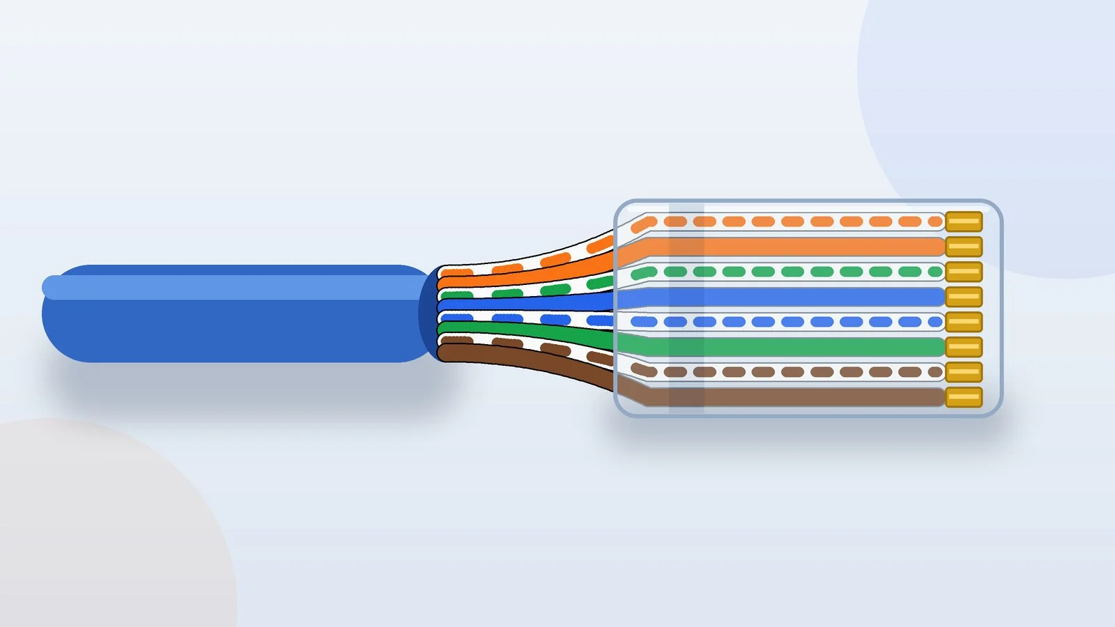
To crimp an Ethernet cable, strip about 2.5 cm of the jacket, untwist the pairs and line up the eight wires in T568B order: white/orange, orange, white/green, blue, white/blue, green, white/brown, brown. Then trim the wires straight, push them all the way into an RJ45 connector and crimp it. The other end gets the same scheme, and the finished cable is checked with a tester.
Below is how to do it right: a color chart for the T568A and T568B schemes, seven steps for standard and pass-through connectors, wiring for a 4-wire cable, testing and the mistakes that leave a cable dead or stuck below 1 Gbps. The guide covers Cat5e and Cat6 UTP cable.
T568A and T568B wiring schemes
The wire order in an RJ45 connector is set by the ANSI/TIA-568 cabling standard. It defines two schemes, T568A and T568B. They differ only in where the orange and green pairs go; the blue and brown pairs sit in the same place. Pins are numbered left to right when you hold the connector with the latch down and the cable pointing toward you.
| Pin | T568B | T568A |
|---|---|---|
| 1 | white/orange | white/green |
| 2 | orange | green |
| 3 | white/green | white/orange |
| 4 | blue | blue |
| 5 | white/blue | white/blue |
| 6 | green | orange |
| 7 | white/brown | white/brown |
| 8 | brown | brown |
In speed and reliability the two schemes are equal: Gigabit Ethernet runs on both. According to Fluke Networks, T568B is more common in home networks. Pick either one, but use the same scheme on both ends of the cable and across the whole network. If the cable goes into a wall jack or a patch panel, follow the color labels on the module: the order of the terminals on the back can differ from the order of the contacts on the front, depending on the maker.
Cut the cable and strip the jacket
Cut the cable to length with a straight, square cut. If you plan to use boots, slide them onto the cable now: they won’t fit over the connector after crimping.
Strip about 2.5 cm of the jacket with the stripper. Make sure the blade doesn’t cut into the wire insulation; if it does, cut off that section and start over. Cat6 cable sometimes has a plastic pair separator inside: trim it off right at the edge of the jacket.
Result: Four twisted pairs stick out of the jacket, about 2.5 cm long.
Untwist the pairs and arrange the wires
Untwist the pairs and straighten the wires by running them between your fingers. Line them up following the chart above; for T568B that’s white/orange, orange, white/green, blue, white/blue, green, white/brown, brown.
With T568B the green wire goes sixth, with the blue pair between it and the white/green wire. That’s not a mistake: pins 3 and 6 must carry one pair. Squeeze the row between your fingers so the wires lie tight and don’t cross.
Result: The eight wires lie flat, side by side, in the order of your chosen scheme.
Trim the wires straight
Cut all the wires with one snip across the row so that about 13 mm remains beyond the edge of the jacket. Treat it as a guide: for Cat5e and higher, the standard allows pairs to be untwisted no more than 13 mm from the point of termination, and the exact length depends on the connector design.
For a pass-through connector, don’t shorten the wires yet: the crimper will trim them after crimping. For connectors with a wire guide insert, follow the maker’s instructions for the order of steps and the wire length.
Result: All wires are the same length, with a clean, straight cut.
Insert the wires into the connector
Hold the connector with the latch down and push the row of wires all the way in, keeping the row steady with your fingers. Each wire must travel down its own channel to the front — you can see this through the clear housing. Check the colors against the chart once more.
The cable jacket must go inside the connector: when you crimp, the plastic strain relief clamps it and takes the load off the wires. With a pass-through connector, push the wires all the way through until they come out of the front.
Result: All eight wires reach the front of the connector, and the jacket is inside it.
Crimp the connector
Push the connector all the way into the crimper’s 8P8C die and squeeze the handles fully. The tool’s teeth press the contacts into the wires, and the connector’s plastic deforms to grip the jacket. A ratcheting crimper won’t open until it has completed the full stroke.
Pass-through connectors are crimped with a crimper that has a blade for them: in the same stroke it cuts the protruding ends flush with the housing.
Result: The contacts are pressed down evenly, and the cable doesn’t pull out of the connector.
Crimp the other end the same way
Repeat steps 1–5 on the other end of the cable with the same color order. Hold the connector the same way, latch down and cable toward you: with T568B the white/orange wire ends up on the left here too.
Result: Both ends are crimped to the same scheme.
Test the cable
Plug the cable ends into the main and remote units of the LAN tester. On a good straight-through cable, lights 1–8 come on one by one, in the same order on both units. A light that stays off means a break or a bad contact on that wire; a different number lighting up on the remote unit means the wires are swapped.
Then connect the cable to your router and computer. If both ports are gigabit, the network connection properties should show a speed of 1 Gbps (1,000 Mbps). Without a tester, you can check a short cable with a multimeter in continuity mode: pin 1 on one end should beep with pin 1 on the other, 2 with 2, and so on.
Result: The tester runs through wires 1–8 in order, and the computer shows a 1 Gbps link.
How to crimp a 4-wire Ethernet cable
A 4-wire cable has two pairs. That is enough only for 10BASE-T and 100BASE-TX, which carry data on pins 1, 2, 3 and 6, so such a cable tops out at 100 Mbps. For 1 Gbps and faster you need all four pairs.
One pair goes on pins 1 and 2, the other on pins 3 and 6, and pins 4, 5, 7 and 8 stay empty. The other end is wired the same way. For orange and green pairs in the T568B scheme it looks like this:
| Pin | Wire |
|---|---|
| 1 | white/orange |
| 2 | orange |
| 3 | white/green |
| 6 | green |
If the second pair in your cable isn’t green but, say, blue, put it on pins 3 and 6 the same way: all that matters is that pins 1–2 and 3–6 each get the two wires of one pair.
If the cable will carry PoE power — to an IP camera or an access point — crimp all eight wires. The power source may feed current over the spare pairs 4–5 and 7–8 (Mode B, which most passive PoE systems also use), and high-power 802.3bt PoE — up to 60 and 90 W at the source — is designed for all four pairs.
Straight-through or crossover cable
A cable with the same scheme on both ends is called straight-through, and it’s what you need almost every time: computer or TV to router, router to switch. A crossover cable is crimped to T568A on one end and T568B on the other. At 10 and 100 Mbps it was needed to connect ports of the same type, such as two computers or two switches.
Today a crossover is rarely needed: ports with Auto MDI-X detect the cable type and adjust to it on their own. It’s enough for one of the two devices to support it. On Cisco Catalyst switches, for example, Auto MDI-X is on by default, but it works only when the port speed is negotiated automatically. A direct connection between two computers comes in handy, for example, to move data from an old laptop to a new one.
Which cable and connectors to choose
| Category | Speed at 100 m | Best for |
|---|---|---|
| Cat5e | 1 and 2.5 Gbps | Internet and networks up to 1 Gbps |
| Cat6 | 5 Gbps; 10 Gbps — up to 37–55 m | Headroom for 2.5 and 5 Gbps ports |
| Cat6A | 10 Gbps | Networks with 10 Gbps ports |
For home internet up to 1 Gbps, Cat5e is enough, while Cat6 leaves headroom for multi-gigabit ports. The category is printed on the cable jacket. Solid-conductor cable goes into walls and raceways; for flexible cords that get moved around a lot, use stranded cable.
The conductors must be copper. CCA cable — copper-clad aluminum — doesn’t meet TIA and ISO/IEC standards: its resistance is about 55% higher than that of copper wire of the same diameter, and it runs hotter when it carries PoE. It’s easy to check: scrape a conductor with a knife — if there’s silvery metal under the copper, it’s aluminum.
Match the connector to the cable: its specs list the category, the conductor type (solid, stranded or both) and the maximum insulated wire diameter. Contacts for solid and stranded wire are built differently, and a mismatch makes an unreliable connection. In pass-through connectors (such as EZ-RJ45) the wires exit through the front, so you can see the color order before crimping.
Shielded cable (F/UTP, S/FTP) needs shielded connectors. The foil is folded back over the jacket, or the drain wire is used, so the cable shield connects to the connector housing — the connector’s instructions tell you exactly how.
The crimper needs an 8P8C die, and for pass-through connectors a model with a blade that trims the wire ends as it crimps. For example, the Platinum Tools EZ-RJPRO HD also works with most standard RJ45 connectors. A basic LAN tester finds breaks, shorts and swapped wires, but it can’t see a split pair. Testers with a pair-aware wiremap, such as the Fluke MicroScanner2, can.
Troubleshooting
- A tester light stays off — a wire didn’t reach its contact, or the contact isn’t pressed down fully. Crimp the connector again, and if that doesn’t help, cut it off and fit a new one.
- The lights come on out of order — the wires are swapped on one of the ends. Find the mistake by the colors through the clear housing and re-crimp that end.
- The tester passes, but the connection drops — check for a split pair (with T568B the green wire goes sixth), for pairs untwisted more than 13 mm, and whether the cable is longer than 100 m.
- 100 Mbps instead of 1 Gbps — in Intel’s experience, the cable is almost always to blame: a damaged Cat5e or Cat6 cable will usually still work at 100 Mbps. Check the blue and brown pairs (pins 4, 5, 7, 8) and make sure it isn’t a 4-wire cable. If the router or computer port itself is rated for 100 Mbps, you won’t get more: when choosing a new router, check its LAN port speed.
- The connector falls out of the port, or the cable pulls out of the connector — the latch is broken, or the jacket didn’t end up under the strain relief. Re-crimp the connector; a boot will protect the new latch from snapping.
- Two directly connected computers don’t see each other — older network cards may lack Auto MDI-X, in which case you need a crossover cable. Also make sure the port speed isn’t set manually.
How to find a break in the cable
A regular tester shows which wire is broken, but not where. If the cable runs in the open, inspect it first: Intel suggests looking for spots where the cable was shut in a door, rolled over by an office chair or stepped on.
Testers that measure length show the distance to a break or a short: the Fluke MicroScanner2, for example, shows how far from the tester the fault is, and it measures cable length even without the remote unit. Managed switches offer similar diagnostics: on TP-Link JetStream switches, the cable test shows the status of each pair and the distance from the port to the fault.
Sources and methodology
Analysis of public sourcesChecked 22 September 2026
- Fluke Networks: T568A vs T568B wiring flukenetworks.com
- Fluke Networks: maximum pair untwist at termination flukenetworks.com
- TIA: ANSI/TIA-568.2-E standard tiaonline.org
- Cisco: Auto-MDIX on Catalyst switches cisco.com
- Intel: Ethernet cabling specifications intel.com
FAQ
Which wiring scheme is correct, T568A or T568B?
Both are defined in the ANSI/TIA-568 standard and work the same, including at 1 Gbps. What matters is using the same scheme on both ends of the cable and across the network. Home networks use T568B more often.
How many wires do you need for 1 Gbps internet?
All eight. Four wires (pins 1, 2, 3 and 6) are enough only for 10BASE-T and 100BASE-TX, which means no more than 100 Mbps.
Can you crimp an Ethernet cable without a crimping tool?
A crimper presses all eight contacts in one stroke and clamps the cable jacket. With a screwdriver you have to push the contacts down one at a time, and you risk leaving one of them short or damaging the housing. If the cable doesn’t need to go through a wall, it’s easier to buy a ready-made patch cable of the right length.
How do you connect twisted-pair cable to a wall jack?
Wires aren’t crimped into a wall jack; they’re pressed into the module’s insulation-displacement terminals following its color labels for your chosen scheme. The order of the terminals on the back can differ from the order of the contacts on the front, so go by the maker’s labels, not the connector chart.
How long can an Ethernet cable be?
Up to 100 m between devices: under the standard, that’s up to 90 m of permanently installed cable plus patch cords. For longer runs, put a switch in the middle.






Leave a Reply